- EL ORIGINAL SOLO CON EL DIAMANTE

Hydrualic switch DN 25/ DN 32 – vertical
1. marzo 2024
Manifold DN 25/ DN 32
1. marzo 2024

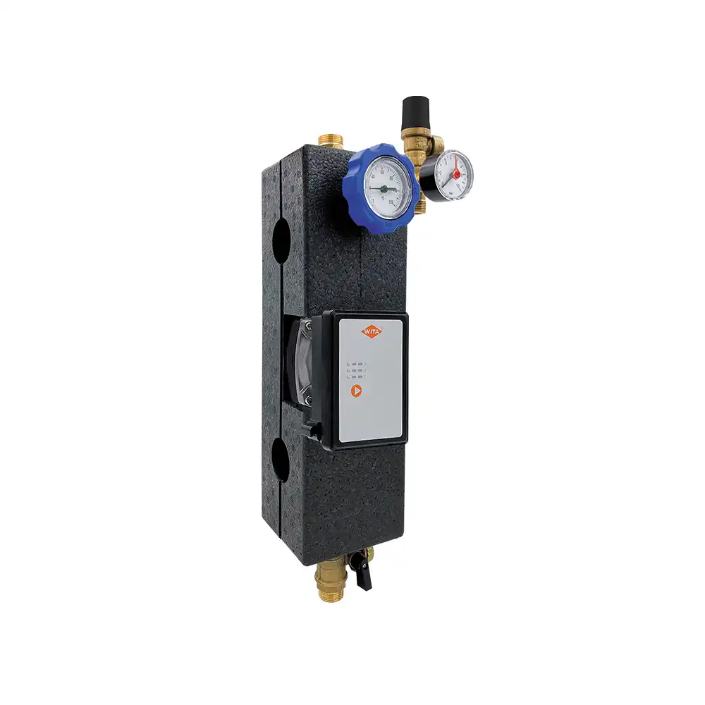
Manifold DN 25 (LDP)
The LDP (low differential pressure) heating circuit manifold hydraulically decouples the primary from the secondary circuit. If different volume flows result from different generation and consumption structures, the water quantity required to compensate for this is diverted via the overflow valve integrated in the manifold, from the flow to the return chamber or vice versa. A faster shutdown of the heating source is possible and pressure fluctuations in the system (due to sudden closing of the secondary circuits) are reduced.
| DN 25 (LDP) | |
| Nominal diameter | DN 25 |
| Connection dimensions | 1 ½“ Rp |
| Center distance heating flow and return flow |
125 mm |
| Dimensions (H x W x L) | 2+1: 190 mm x 160 mm x 550 mm 3+2: 190 mm x 160 mm x 800 mm |
| Materials | EPP, brass, steel, EPDM seals |
| Field of application | 140 kW (∆T = 20 K), up to 100 °C, Kvs 13 m³/h, 110kW 140 kW (∆T = 20 K), |
| Operating pressure | max. 6 bar |
| Maximale Förderhöhe | |
| Maximaler Durchfluss | |
| Leistungsaufnahme | |
| Regelung | |
| Versorgungsspannung | |
| Motorschutz | |
| Schutzart | |
| Umgebungstemperatur | |
| Medientemperatur | |
| Temperaturklasse | |
| Systemdruck max. | |
| Anschlussgrößen | |
| Einbaulängen | |
| Material Pumpengehäuse | |
| Gewicht inkl. Isolierung | |
| EEI | |
| Sonderaustattung |